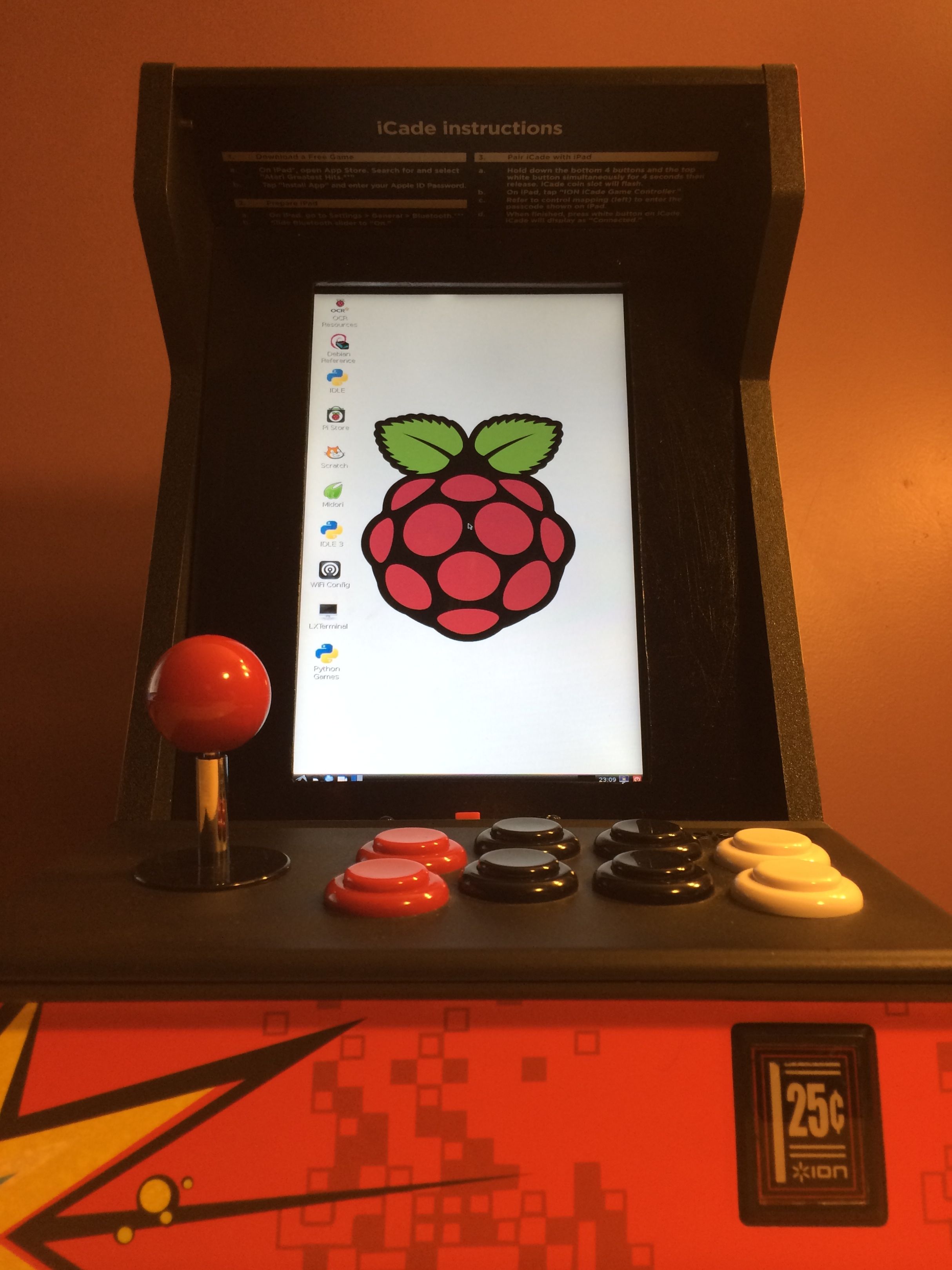
ICADE RASPBERRY PI MOD
Hardware
Display:HDMI 10.1″ 1280×800 IPS
https://www.adafruit.com/products/1287
Computer Hardware:
Raspberry Pi (Model B) + SD Card with Raspbian Wheezy Installed
http://www.adafruit.com/products/998
http://www.adafruit.com/products/1121
Coin Slot Hardware:
Used a cap-touch sensor to simulate coin drop.
http://www.adafruit.com/products/1374
Other:
USB Hub
Cheap-O USB Powered Speaker
Sintra board used for LCD bezel and back cover
Various mounting hardware I had lying around
Mounting the Raspberry Pi
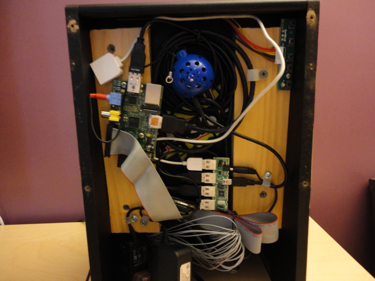
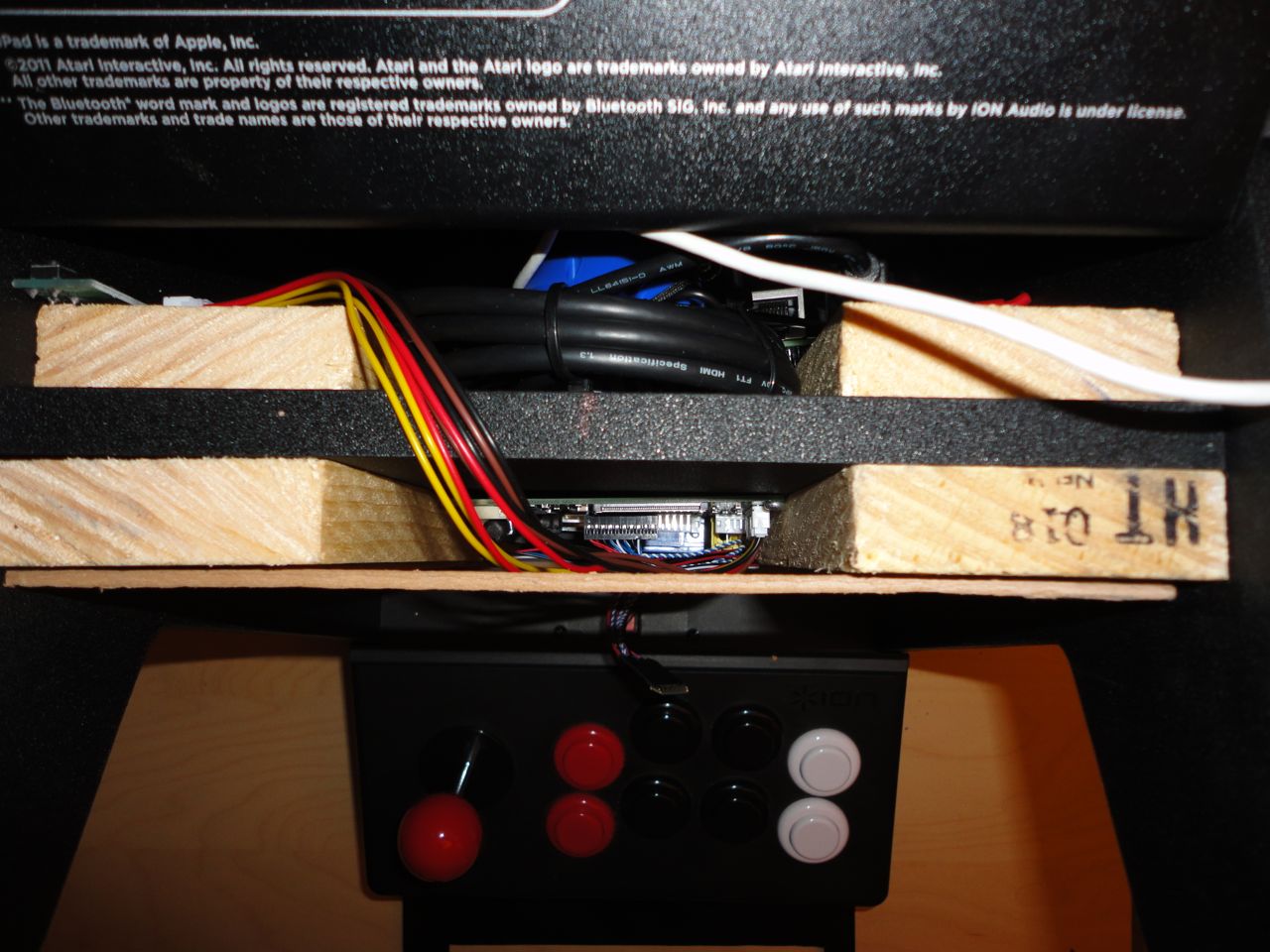
To mount the Raspberry Pi (RPi), USB hub, power supplies and speaker, I used some 3/4″ thick pine boards I had lying around. Cut them to length and screwed into the back of the iCade cabinet. I also removed the USB hub’s enclosure to make sure it’d fit with the back panel on. I used plastic wire mounting clips to keep all the wiring neat. The space between the pine boards was used as a channel for the bulk of the wires (HDMI, USB, power).
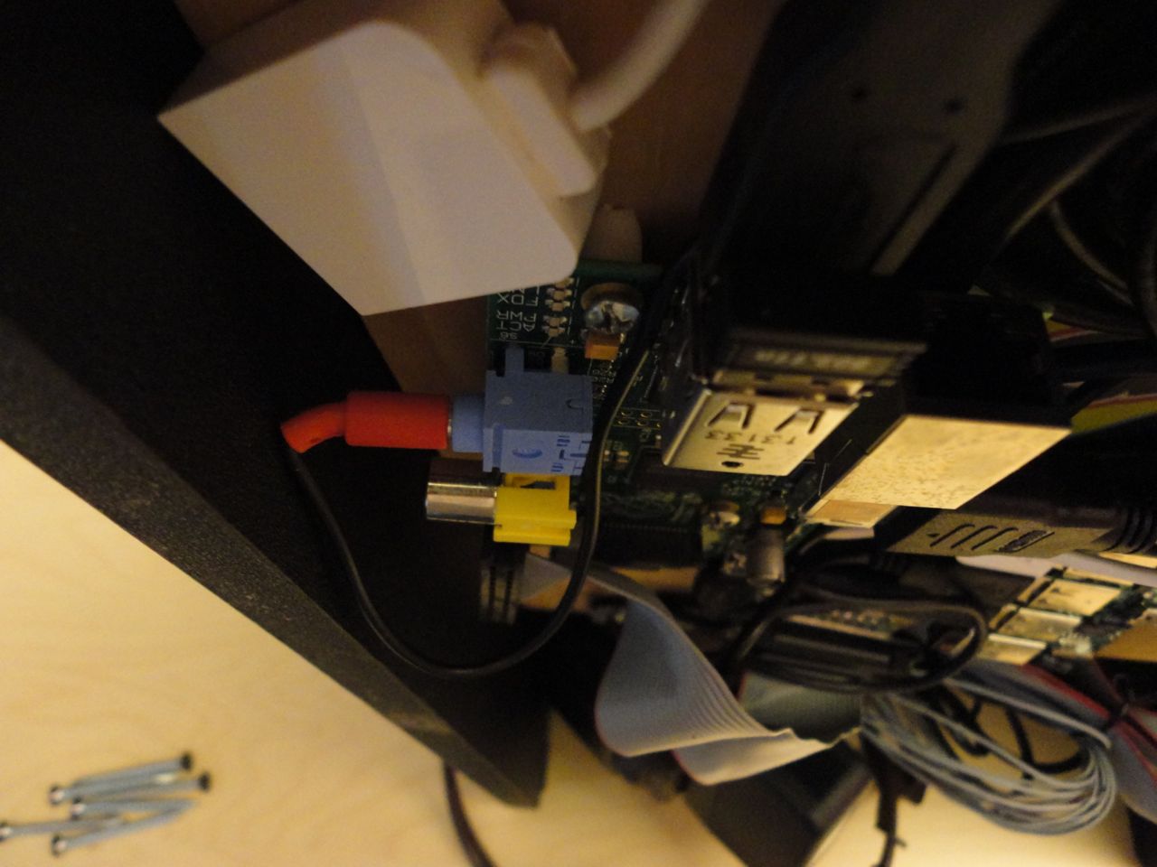
I used some “modified” plastic spacers for mounting the RPi to the pine boards. The Pi had to be mounted on an angle to allow the 1/8″ audio cable to squeeze in.
Power Supply
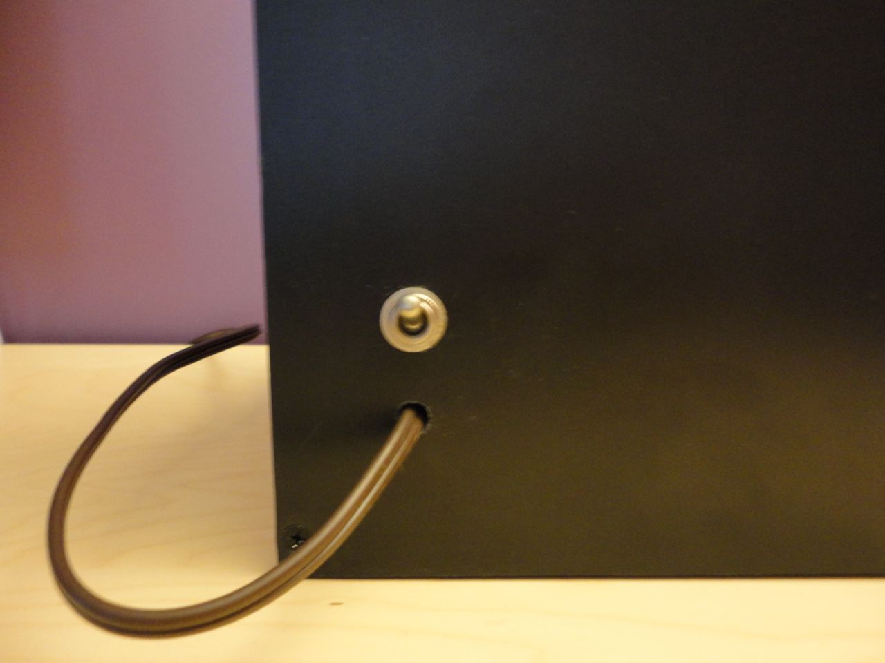
I wanted to be able to power the cabinet without needing an AC/DC power supply external to the cabinet. To accomplish this, I used an old 120VAC toggle switch I pulled from an old piece of audio equipment and wired in an extension cord to supply power to the cabinet. Inside the cabinet, I simply plugged the USB hub’s and LCD’s wall wart power supplies to the extension cord. The USB hub supplies power to the speaker and the RPi.
Mounting the LCD
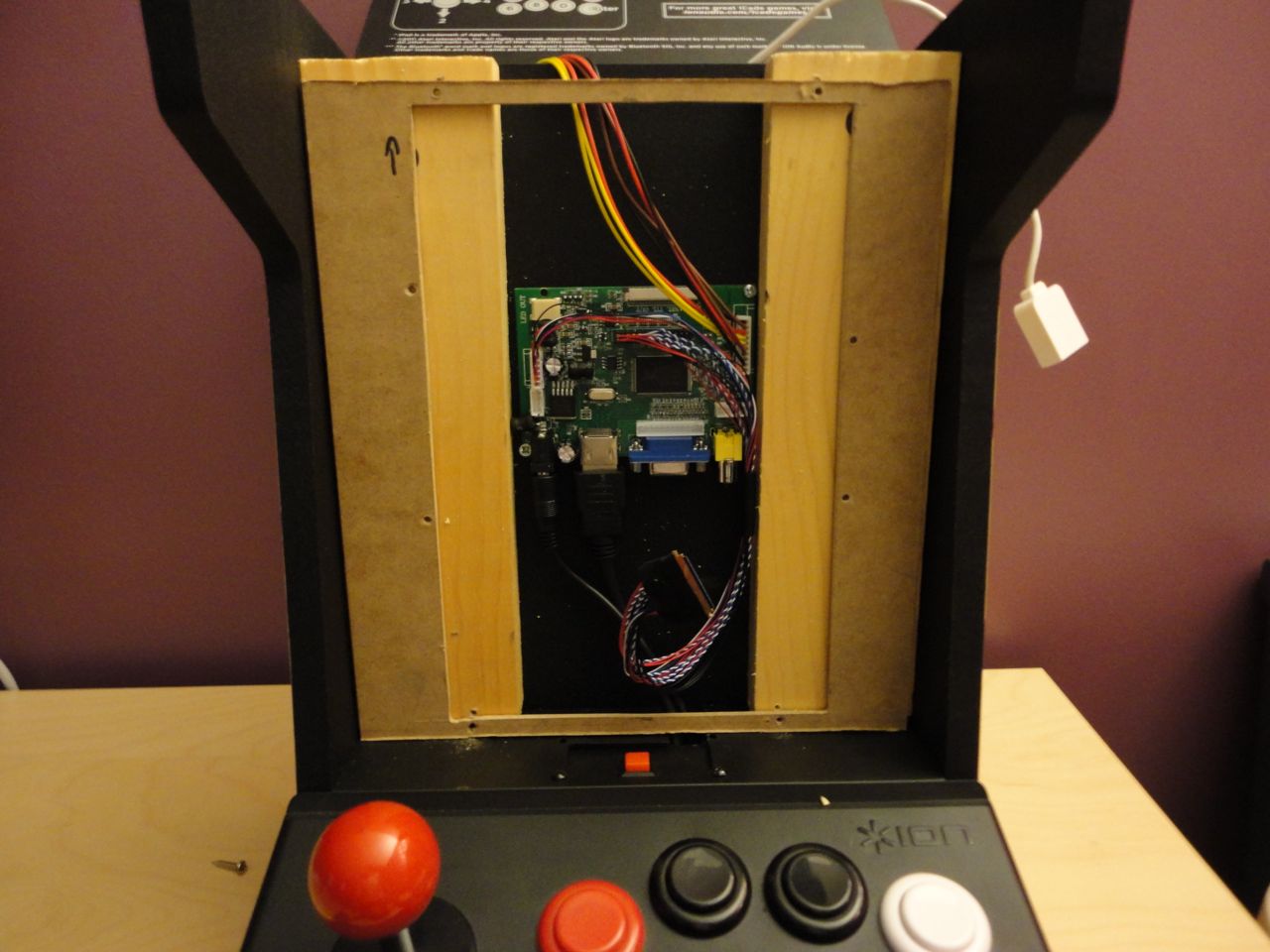
To mount the LCD I used some pine boards and some spare MDF board as riser/spacer. The MDF allowed enough space for the the LCD connector needed to connect the LCD panel to the driver board (seen between the pine boards). The DC power and HDMI cables were run between the pine boards and fished through the the existing cutout used for iPad charging in the iCade’s past life.
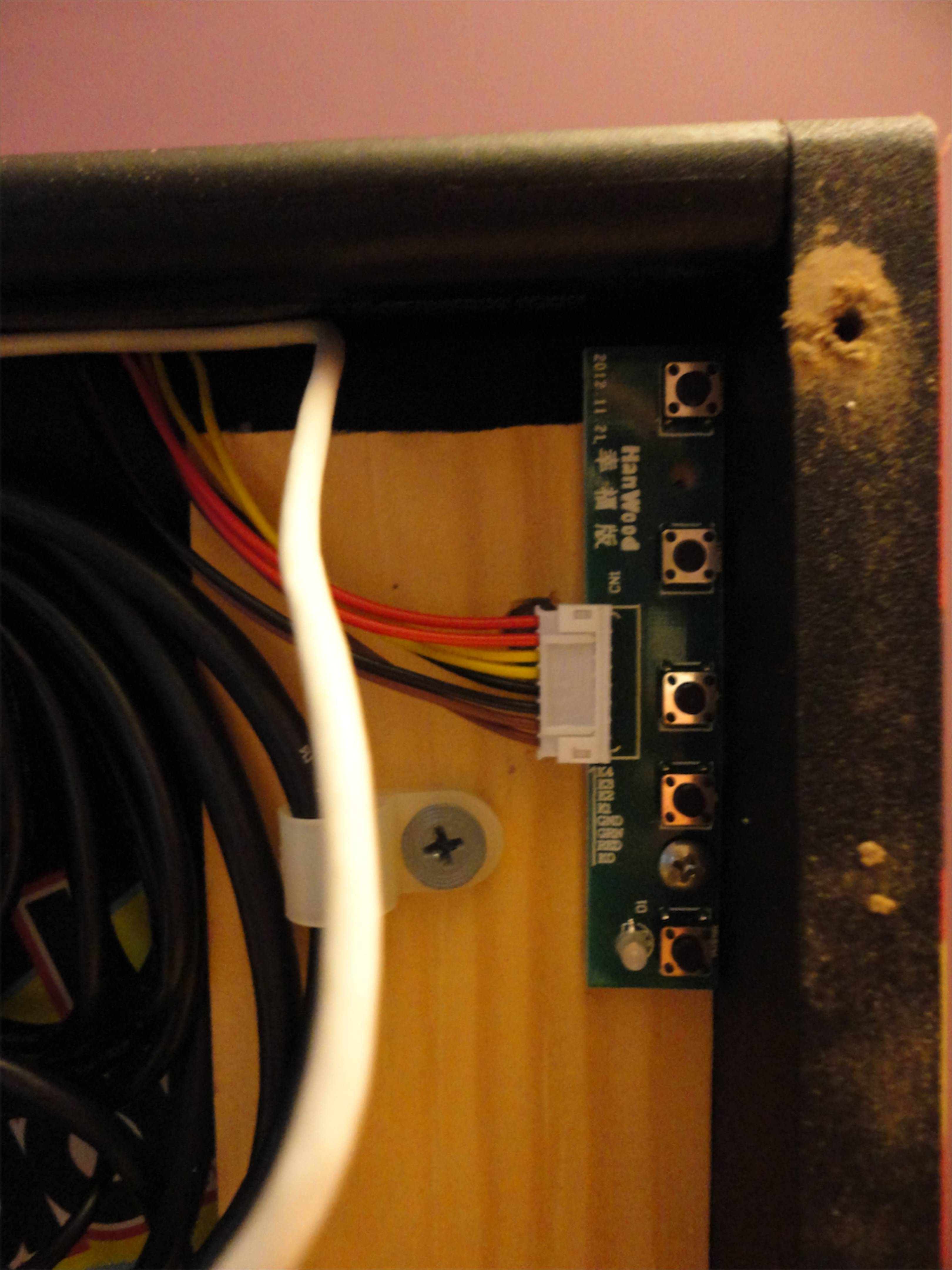
Ran the LCD monitor switch panel wiring over the top of the cabinet.
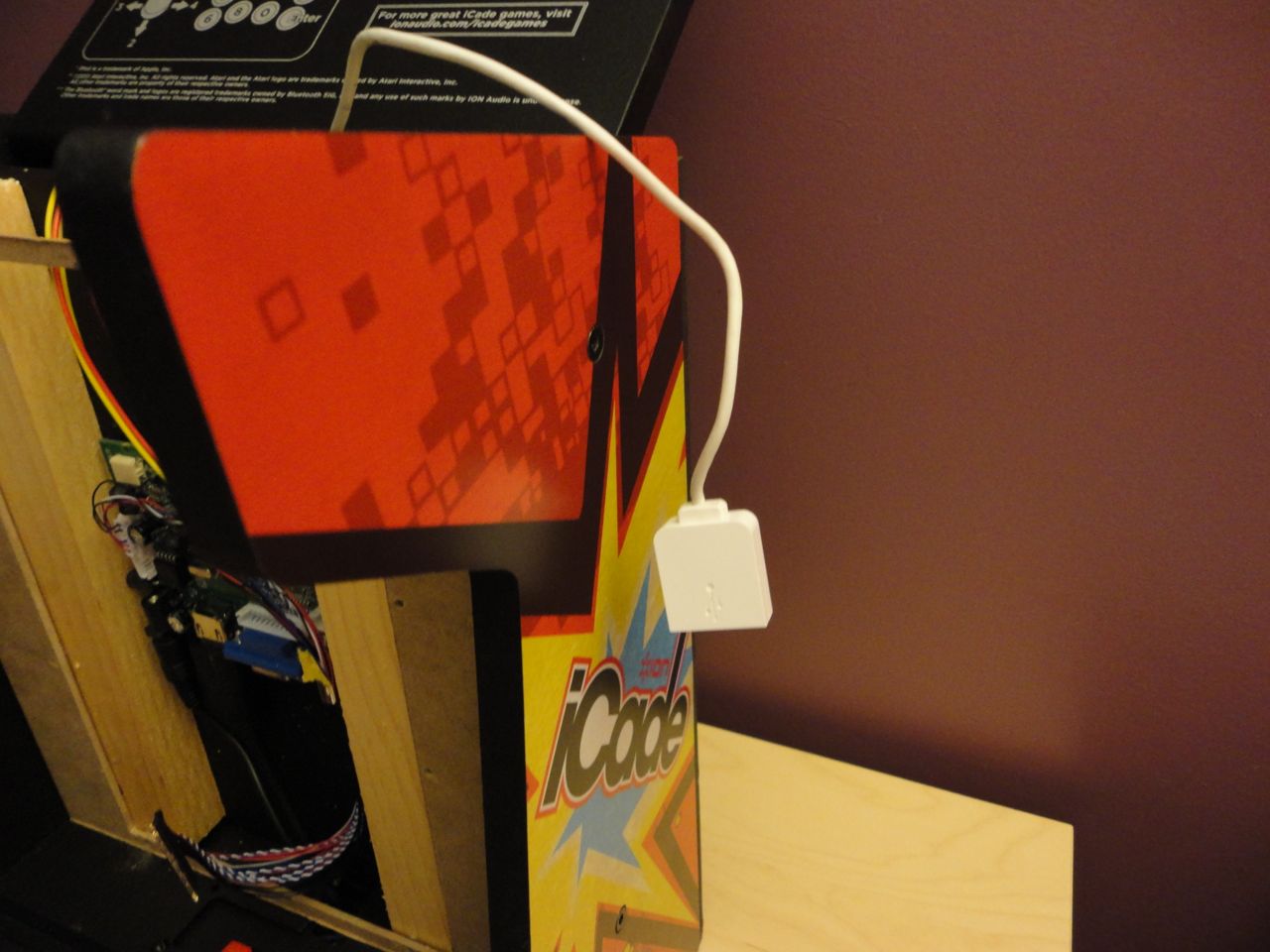
I added a USB extension cable to allow the connection of a USB flash drive, mouse, keyboard, etc.
Originally, the iCade cabinet had a channel for running a cable to charge the iPad during play. I reused this channel (with some minor modifications) for running the LCD’s HDMI and DC power cables.
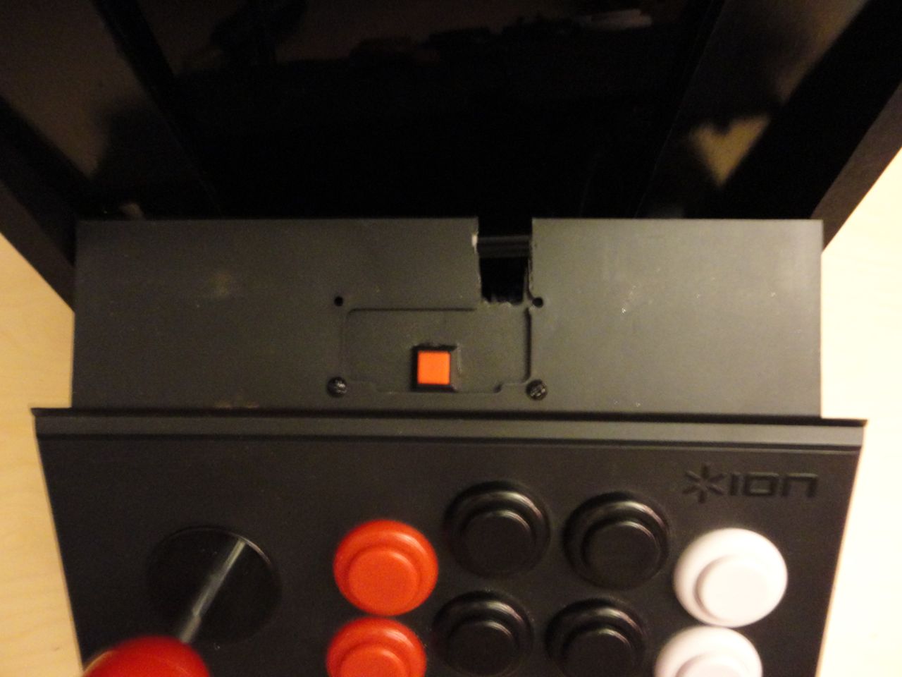
Cut out on joystick panel for LCD cabling (don’t worry, bezel covers up this ugliness). Square button was added as a dedicated “escape” input to allow user to exit current MAME game.
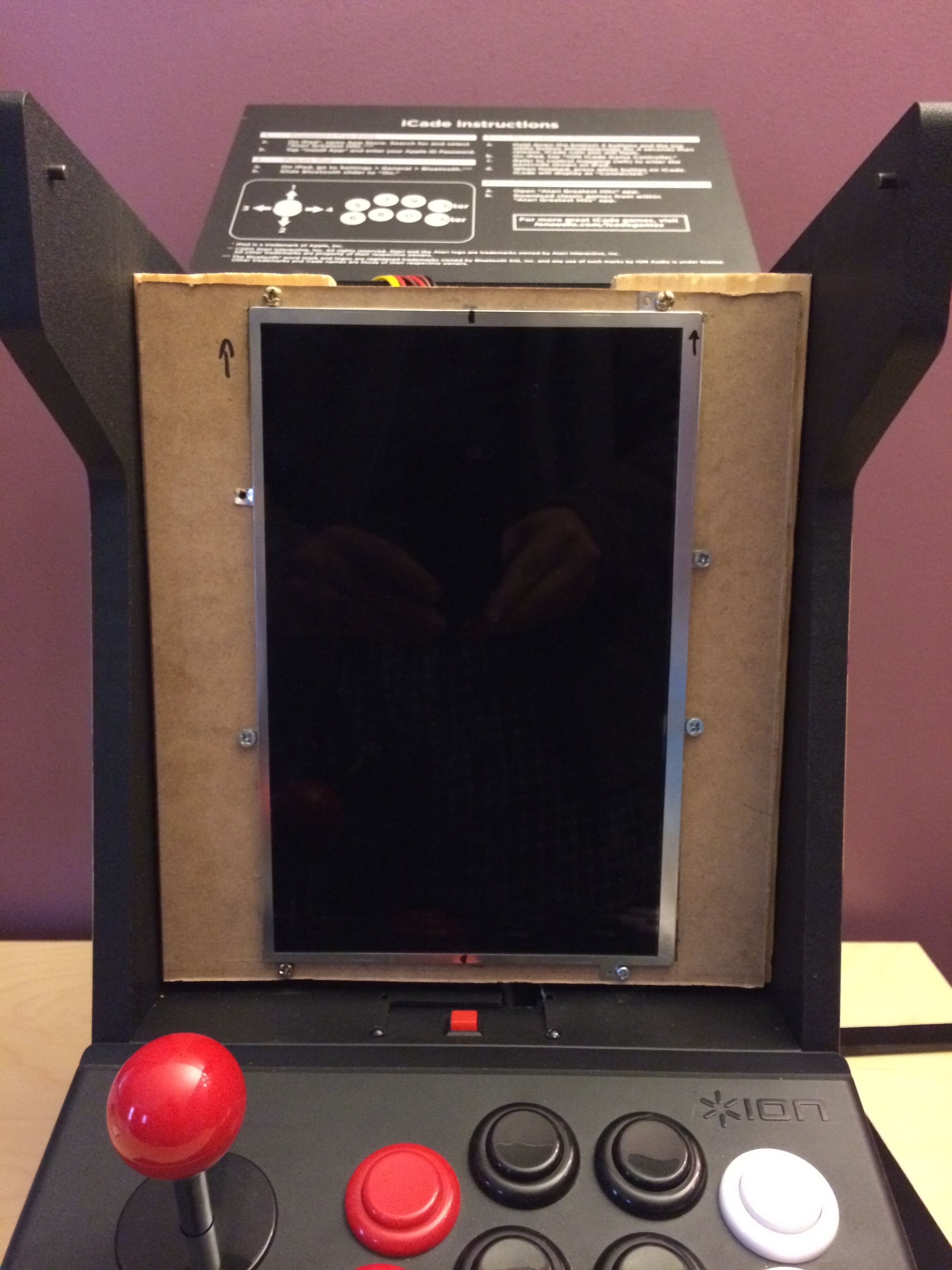
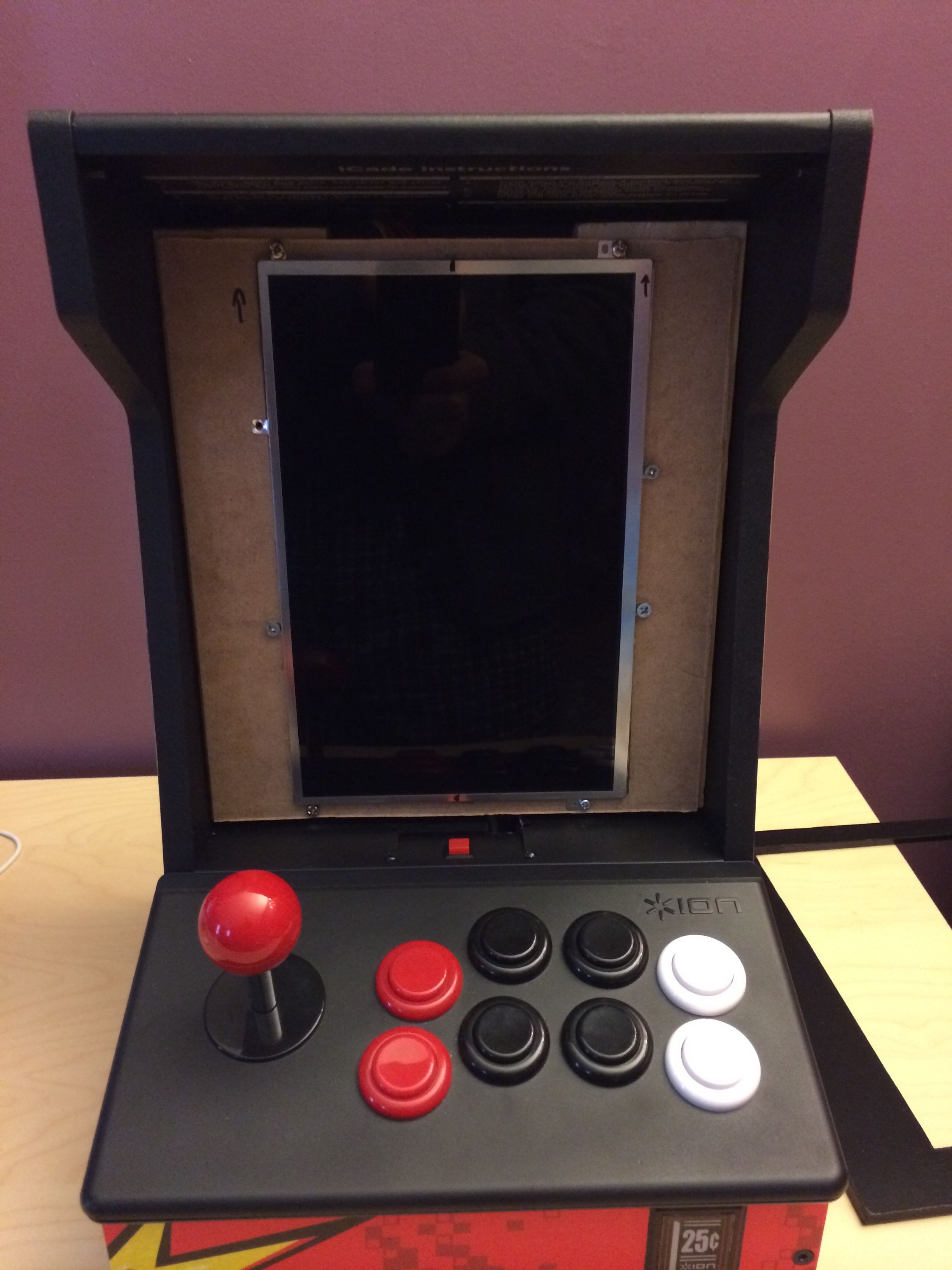
LCD mounted.
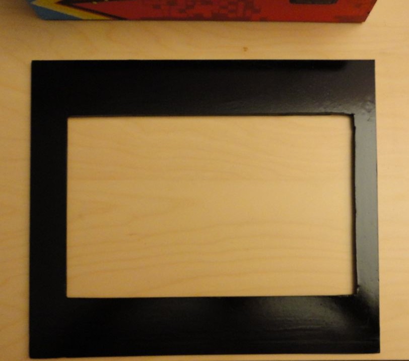
Used some spare Sintra board I had for the LCD bezel. Made the cutout using a utility knife, however, using the Dremel would’ve probably worked out a little better. Lightly sanded the surface and then spray-painted it black.
Joystick and Buttons Wiring
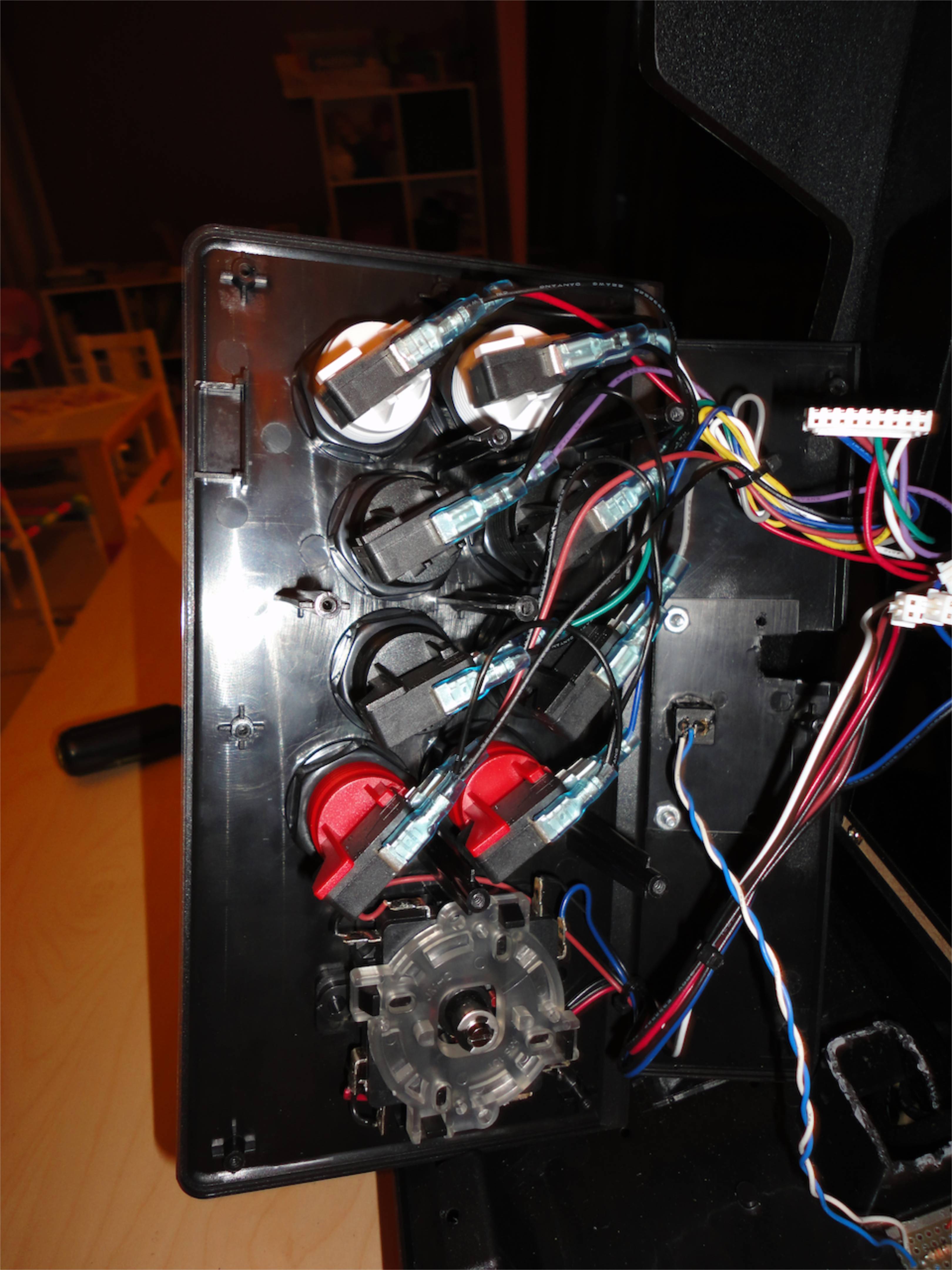
To connect the control panel (joystick, buttons) to the RPi I decided to ditch the Bluetooth HID board that came with the iCade and wire the switches in directly.
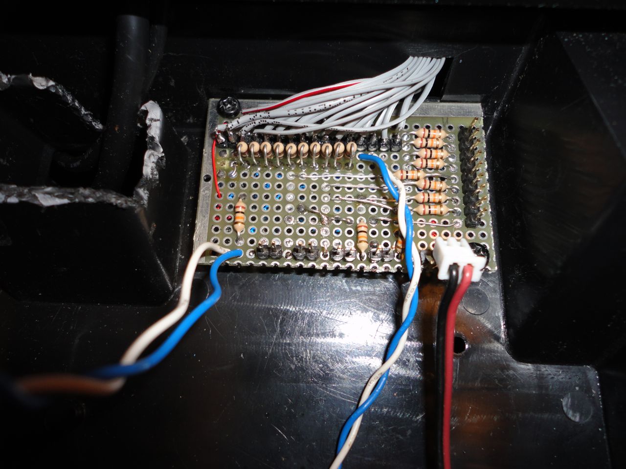
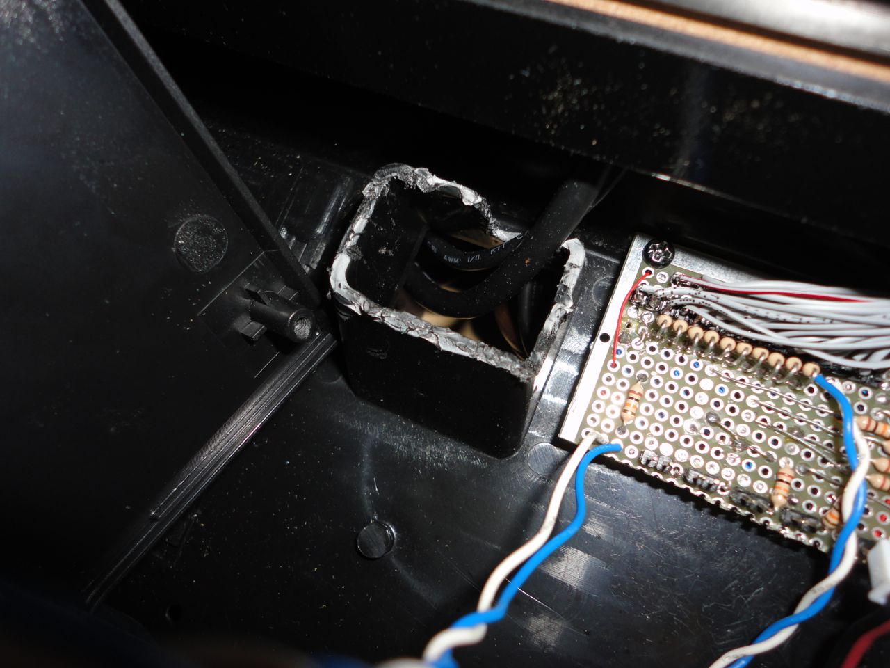
Cut one end of a 26pin ribbon cable to connect up joystick and button inputs to the RPi. I separated each conductor of the 26pin cable, pulled them all through old DC power plug port. I had enough slack in the cable that it wasn’t too difficult to solder the wires to the protoboard in this fashion. I used external pull-up and current limiting resistors to interface the buttons with the RPi’s GPIOs, although, I probably could’ve just used the internal pull-ups and been fine. Here’s a good intro to interfacing your RPi with buttons/switcheshttp://www.cl.cam.ac.uk/projects/raspberrypi/tutorials/robot/buttons_and_switches/
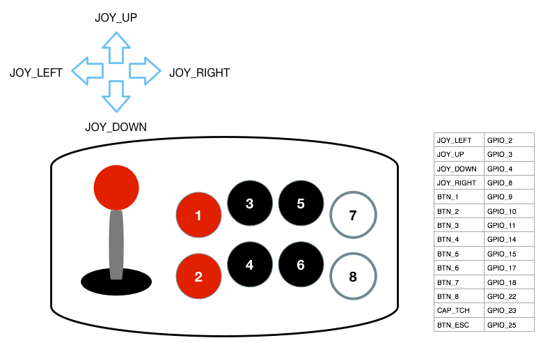
GPIO Mapping Table


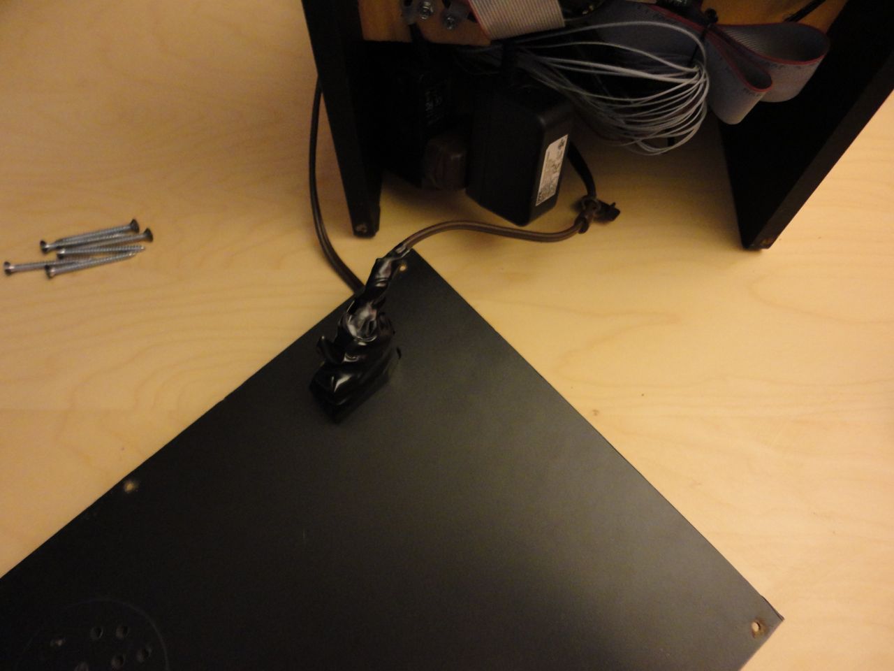
Bottom view of the cabinet with all the cables.
Coin Slot
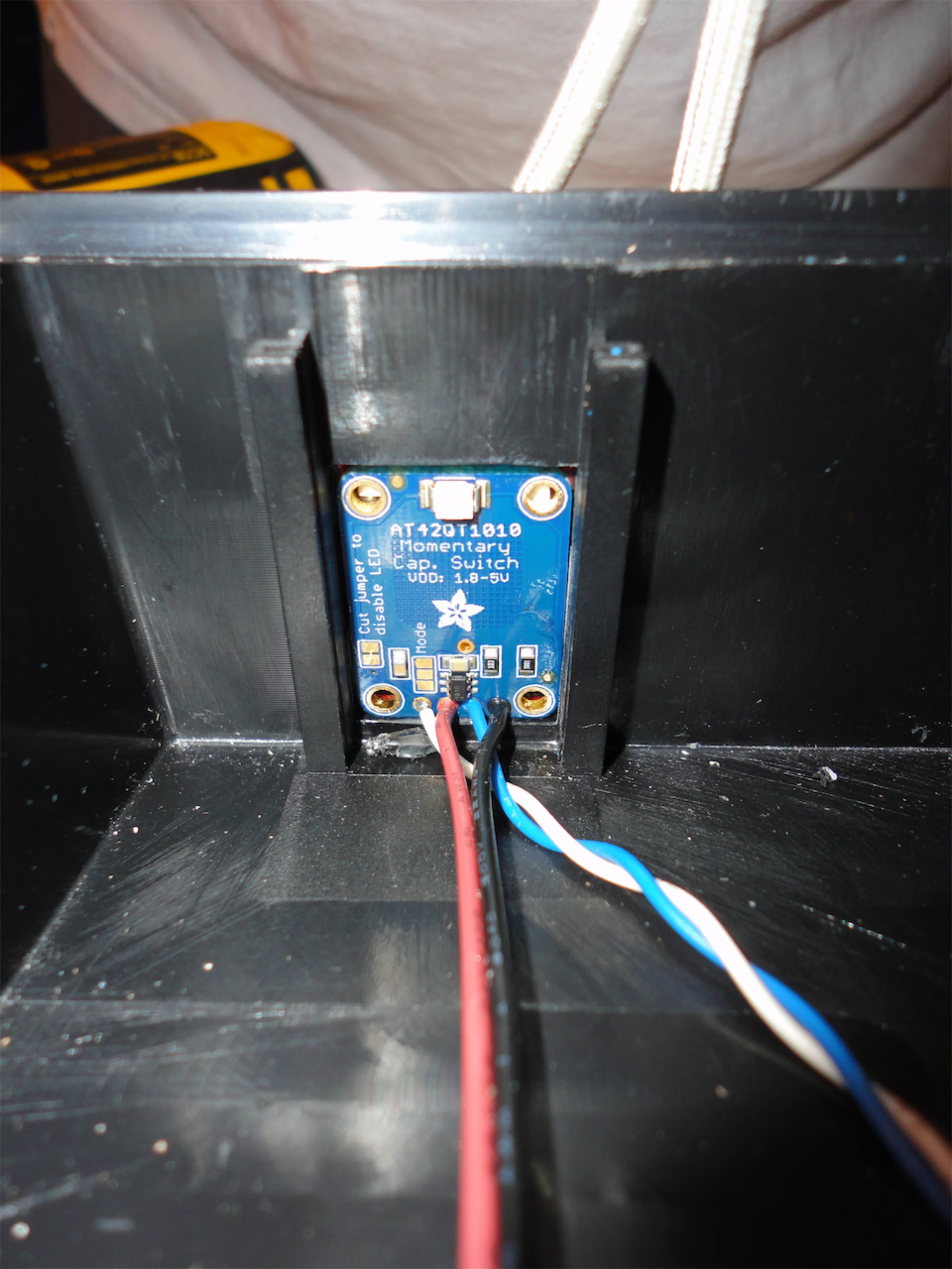
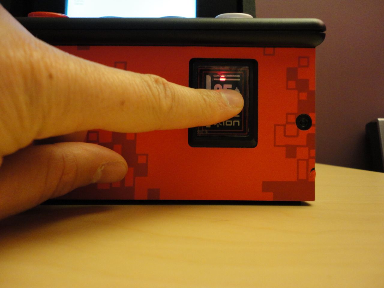
For the coin slot I decided to go with a cap-touch sensor to simulate the coin drop. Found the AT42QT1010 based sensor module from Adafruit, it fit perfectly in the coin slot cut-out. I removed the original LED board, and just crazy glued the cap-touch sensor module to the plastic, 25 cent cover. Looks fantastic and lights up when you touch the sensor.
Software
I’m running Raspbian Wheezy on my RPi since its what came preinstalled on the SD card I purchased. I went with MAME4ALL (https://code.google.com/p/mame4all-pi/) since I heard it was optimized for the RPi.To map the GPIO inputs to keyboard keys, I used Adafruit’s retrogame utility (https://github.com/adafruit/Adafruit-Retrogame). To work with my setup, I needed to make a few modifications to “retrogame.c” though. Since I used external pull-ups for my button inputs, I simply commented out the section of code that enabled the internal inputs (lines 194-214). Also, the IO table needed to be updated to map all game buttons, joystick inputs, escape button and coin slot inputs. Here’s my modified version of the table:
struct {
    int pin;
    int key;
} io[] = {
// Input Output (from /usr/include/linux/input.h)
    { 3, KEY_LEFT },
    { 8, KEY_RIGHT },
    { 2, KEY_UP },
    { 4, KEY_DOWN },
    { 9, KEY_LEFTCTRL },
    { 10, KEY_LEFTALT },
    { 22, KEY_1 },
    { 17, KEY_2 },
    { 23, KEY_5 },
    { 18, KEY_ENTER },
    { 25, KEY_ESC },
};
#define IOLEN (sizeof(io) / sizeof(io[0])) // io[] table size
Since the cap-touch sensor (connected to GPIO23) is active-high, the code needed to interpret it differently since all the other GPIO inputs are active-low. Otherwise, the coin-drop will constantly retrigger. Replace line 226 with the following code:if (io[i].pin == 23)
pinConfig(io[i].pin, "active_low", "1");
else
pinConfig(io[i].pin, "active_low", "0"); // Don't invert
I can’t remember if I needed to modify mame.cfg for MAME4ALL, here it is just in case:[config] artwork=yes samples=yes antialias=yes translucency=yes skiplines=0 skipcolumns=0 beam=1.0 flicker=0.0 gamma=1.0 frameskip=auto ror=no rol=no flipx=no flipy=no samplerate=44100 volume=0 cheat=no vector_width=640 vector_height=480 kioskmode=no force_stereo=no # Anti-alias the display? display_smooth_stretch=yes display_border=0 # display effect postprocessing: 0 none, 1 scanlines display_effect=0 [directory] inp=inp nvram=nvram hi=hi cfg=cfg snap=snap memcard=memcard sta=sta artwork=artwork cheat=. rompath=roms samplepath=samples [frontend] #Keyboard controls for frontend only # Get codes from /usr/include/SDL/SDL_keysym.h K_START=13 K_SELECT=53 K_LEFT=276 K_RIGHT=275 K_UP=273 K_DOWN=274 K_A=306 K_QUIT=27 #Joystick controls for frontend only J_START=9 J_SELECT=8 J_A=0 AXIS_LR=0 AXIS_UD=1


I found your this post while searching for information about blog-related research ... It's a good post .. keep posting and updating information. 3257w
RépondreSupprimer